
3d civil autocad drill - 3d civil autocad drill dwg
.")
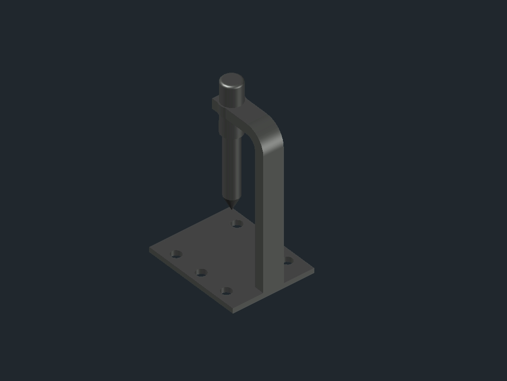
-the base was made; for which 1 rectangle of 200x160 was drawn. on it, 6 circles of 10 mm radius are drawn. the distance between each circle is 60 mm; while the distance of each circle located at the ends is 40 mm from its center to the width of the rectangle and 20 mm from the center to the length of the rectangle. after; _presspul of 10 mm is applied to obtain the raised image in 3d. -the column was made; for which a rectangular prism of 40x20x300 was drawn. -the head was made; for which first 2 circles are drawn: one with a radius equal to 40 mm and another internal one with a radius of 20 mm. the figure was cut in such a way that the fourth part was obtained and they were put together to obtain 1 single figure; no separate lines. later; a 40 mm extrusion was applied. later; 1 rectangle of 60x40 was drawn and 2 circles were drawn; one with a radius equal to 20 mm and an internal one with a radius equal to 15 mm; taking as center for both the midpoint of the width of the rectangle. it was trimmed; the lines were joined in order to obtain 1 single figure and 20 mm _presspul was applied. -the tool holder (chuck) was made; for which 2 circles were drawn: one with a radius equal to 20 mm and another internal one of 15 mm. after; _presspul of 100 mm was applied. -the tool (drill) was made; for which 1 cylinder of 15 mm radius and 120 mm high was drawn and later; 1 cone of 15 mm radius and 30 mm high was drawn. -by last; the parts are placed or assembled in their respective place and with the _union command; these parts are joined to obtain the hole shown in the image.